Inhaltsverzeichnis
Last change: 19.10.2025
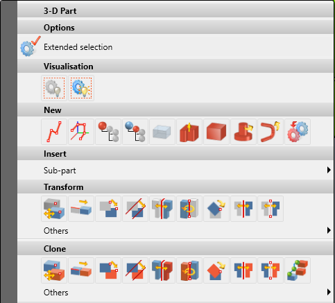
How to produce folded sheets correctly
In this video, I show different methods for creating edge plates in HiCAD, starting with a basic plate. I explain in detail the basic options for installation and go into the meaning as well as the possibilities of the different options. I also explain how to use other semi-finished products for the design.

Afterwards, I explain the next option, how to create a basic sheet in HiCAD based on a sketch. In particular, I explain the importance of the installation direction, since this has a decisive influence on the further design process, especially if sheets have to be replaced later.

Finally, I explain the item 'Sheet metal along sketch', which can be used to create a sheet metal cross section, regardless of whether it is an edge sheet or a composite sheet. I show how a milled sheet can look in the preview and explain the meaning of the installation direction in the section view.

Fold the tab on the sheet metal
In this video, I show how to work with the 'Edge Plate' command in HiCAD and how to use the many options available for processing sheet metal. I explain the different options available for the 'Edge Plate' and how you can even create a milled edge from a bend zone.

I then explain how to edge the tabs on all sides of a rectangular sheet or a polygon with just one step.

This method makes the creation of very complex edge plates in HiCAD easy and fast.
Cutting and mitering sheets
In this video I explain how to extend a sheet in HiCAD using the 'Trim' command. I show the different options for trimming individual tabs or the entire cross-section.

In the second part of the video, I explain how to miter the different tabs on one sheet. It is important to remember that this command can also be used to cut miters on two different sheets. In the dialog box, the respective options are set, and it is clearly shown how diverse the possibilities are here.

Continue copying edge sheets
In this video I show how to copy an edge sheet in HiCAD. To do this, click on the sheet with the left mouse button, then hold the left mouse button and click with the right mouse button to move one structure higher in the ICN.
Connect 2 sketches with connecting plate
In this video I show how to design complex sheets in HiCAD by connecting lines in 2D sketches. This allows you to seamlessly switch between round and angular transitions.
However, the module or license is required for this Sheet metal professional required.

Create folded sheet metal on a part
The 'Sheet on Surface' command in HiCAD provides the option of placing a sheet on a 3D part. This opens up the option of creating even very complex sheets where it would otherwise be difficult due to angles and surfaces.
An example of what you could do with it, would be a Attikablech, which goes around the corner and where the sloping edge is not welded but edged. I already have a somewhat older video on YouTube. ->Link to the video (This video will be recorded again in the future so that it is also state-of-the-art.)
However, the module or license is required for this Sheet metal professional required.

This command has been revised in HiCAD 2022 and now offers new options, including milled bend zones and extended preview options.

Edge tabs using sketches
The 'tab along sketch' command in HiCAD makes it very easy to add a tab to a sheet along a sketch path, avoiding the need for repeated individual calls to the tab function.

In addition, the function can also be selected directly on all edges, allowing you to process a sheet on all sides with just a few clicks.
Coating side for edged sheets
Die Beschichtungsfunktion ermöglicht es, die Ausgabe für Abwicklungen, Stücklisten und Werkstätten Zeichnungen in HiCAD sehr einfach zu optimieren. Auf diese Weise kann man in Werkstätten Zeichnungen leicht angeben, auf welcher Seite die beschichtete Seite ist.

In the parts list, only the coated side is output as the surface. In the parts list 'Edge plate with picture' you can also see the cross-section with the coated side.
Create parts list for folded sheets
In this video I explain how the output of the parts list looks like. When transferred to Excel, the cross-section of the sheet is also output in the table 'Edge sheet with picture'.

In HiCAD 2024, a new template has been extended in the Excel list to make the parts list even more appealing and easier to read. However, this must first be set.

Generate unfolding of folded sheets
In unwinding, certain criteria are decisive in how an unwind is created. When using the automatism, the unwinding is created from top to bottom (see picture below). Therefore, it is extremely important to add these additional options to the edge sheet.

Of course, there are many more options available in the entire dialog. There you can make a variety of settings to optimize the processing from the display to the dimensioning and any labeling.

In addition, many more individual settings can be defined in the advanced settings. These settings can be saved as favorites, so you should define them only once, but once correctly.

Output all sheets as DXF for the laser
In this video I explain how to export all sheets of a construction as DXF. These sheets are of course exported in unrolled form and can be adjusted to different requirements. Don't forget to save your settings as a favorite so you don't have to do them over and over again.

Adjust bending zones correctly
Bending zones are of crucial importance for unwinding. However, it is advisable to create the bending zones only at the end, otherwise certain functions can no longer be performed.
The bending zone can sometimes look strange in 3D and possibly lead to collisions. However, its main purpose is the optimal creation of the unwinding for laser or nipple machines.

Position number on settlement definition
With the function 'Text position on unwind' you have the possibility to define the position of the position text on the unwind to better control the production process.
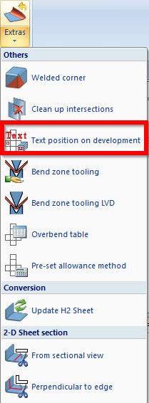
This function requires the “Sheet Metal Professional” expansion module.
You will find more detailed instructions on how to set up and further process the DXF output in the next step. here.
Use bending simulation for complex sheet metal
With bending simulation, you can temporarily unbend a sheet to create highly complex sheets. This is because some machining operations can only be completed in unrolled form.

However, there are many other tests that can be run on the design after the fact to determine the sheet's edging capabilities.
Check settlements for collisions
Durch diesen Test innerhalb des Design Checkers lassen sich Bleche sehr schnell auf ihre Kollisionsfreie Abwicklung prüfen.

Unfolding 3D parts
As of HiCAD 2023, there is also a dialog for the 'Unwind surface' command. This has been completely revised and now works in a similar way to the dialog for sheet metal unfolding.

Changing the length of sheets
Bei der HiCAD 2023 Softwareversion wurden die Funktionen der Befehle ‘Länge ändern mit Punkten’ und ‘Länge ändern’ zusammengeführt, was zu einer deutlichen visuellen Änderung in der Ribbon-Benutzeroberfläche führt.

In the new dialog, all commands have been combined and brought into a uniform structure. This makes it possible to need only one command for it and then to continue it again and again instead of starting several commands one after the other.

Mit welche Befehl kann man am beste Bech teilen und das sie auch in Frature bleiben??
Hallo Martin, der Befehl teilen wurde ja in 2502 bereits überarbeitet. Dazu werde ich so und so noch ein Video machen. Jedoch ist es so, das im nächsten Schritt der Überarbeitung dieses Befehles auch das Teilen von Kantblechen möglich sein wird. Ich bin mir jedoch derzeit noch nicht sicher ob dies bereits in der MR von 2600 sein wird oder erst ein einer Folgeversion. LG
Hallo Martin bei der Ausgabe von mehreren abwiklungsblechen hätte ich gerne alle Bleche in einer DFX ist das nicht möglich ? lg Peter
Ja dazu müsstest du die Zeichnungen vorher so einstellen, das alle Abwicklungen auf einen Blatt im Maßstab 1:1 drauf liegen. Danach kannst du dann einfach diese als dxf speichern. LG Michael